Shift Register with Arduino
Learn to use a shift register with 8 LEDs and an Arduino
Written By: Cherie Tan
Difficulty
Medium
Steps
15
At some point in time, you may need to use more pins than is available on the Arduino. One way to add additional inputs and outputs is to use shift registers. A shift register is a form of sequential logic, composed of a group of flip-flops. A flip-flop is a circuit that has two states, you can also think of it as a basic storage element that can store a binary digit.
In this guide, we will learn how to connect 8 LEDs to the Arduino while only using 3 digital pins instead of 8!
Complete this guide to understand the basics of using a shift register.
At some point in time, you may need to use more pins than is available on the Arduino. One way to add additional inputs and outputs is to use shift registers. A shift register is a form of sequential logic, composed of a group of flip-flops. A flip-flop is a circuit that has two states, you can also think of it as a basic storage element that can store a binary digit.
In this guide, we will use an 8-bit shift register, the 74HC595 integrated circuit. By using it, you can control 8 outputs by only using 3 digital pins on the Arduino.
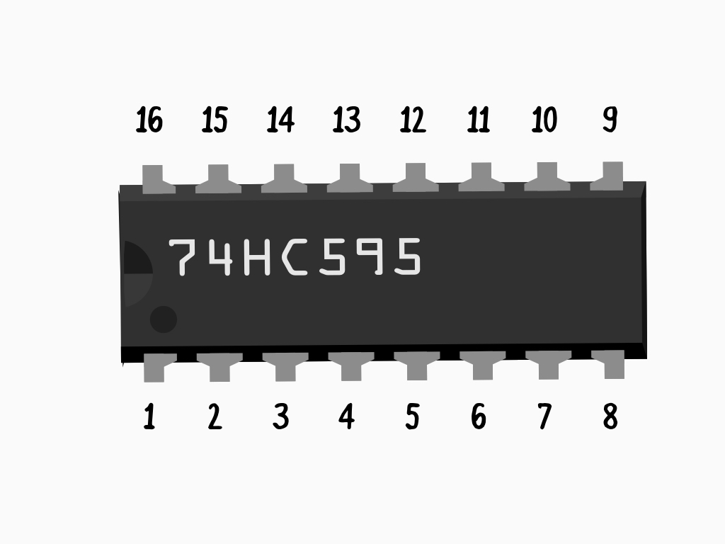
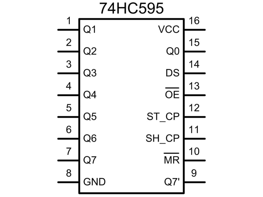
Pin-out for 74HC595 Shift Register:
- Q0 to Q7 (Pins 1-7, and 15) are Output Pins
- Pin 8 - GND (Ground)
- Pin 9 - Serial Out
- Pin 10 - Master Reclear, active low
- It will clear the shift register when pulled LOW.
- Pin 11 - Shift register clock pin
- It will shift the register when pulled HIGH.
- Pin 12 - Storage register clock pin (latch pin)
- For the pattern of bits to be output by the shift register, it needs to be pulled HIGH
- Pin 13 - Output enable, active low
- Enables output when pulled LOW, disables output when pulled HIGH.
- Pin 14 - Serial data input
- Pin 16 - VCC (Positive supply voltage)
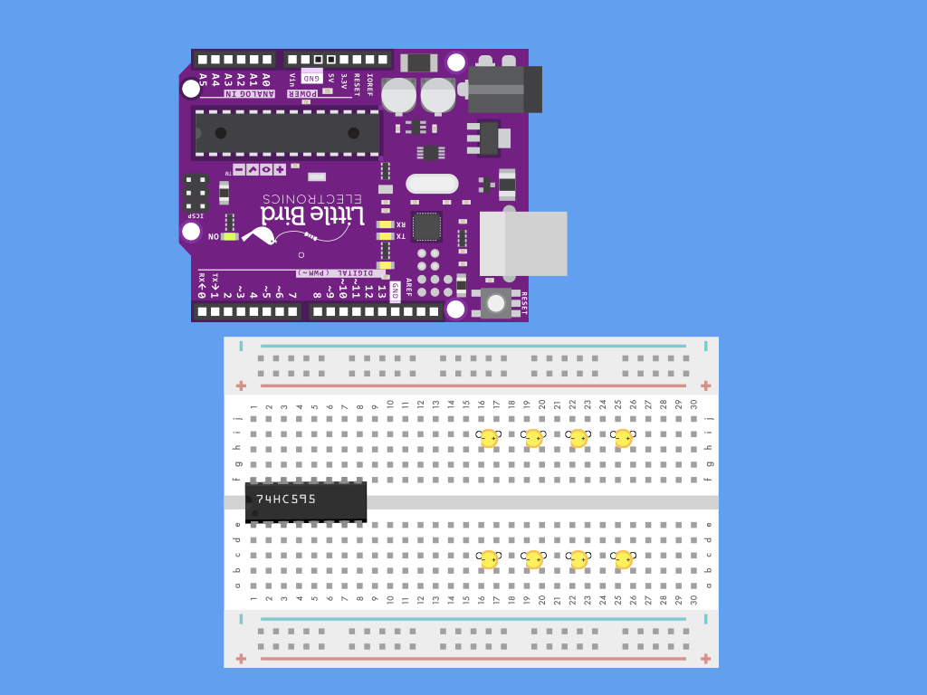
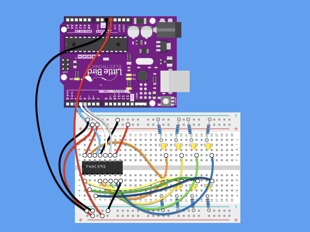
First, connect the shift register to the breadboard.
- Make sure the little notch on the shift register IC is facing the bottom left corner
Then connect 8 LEDs to a breadboard as shown.
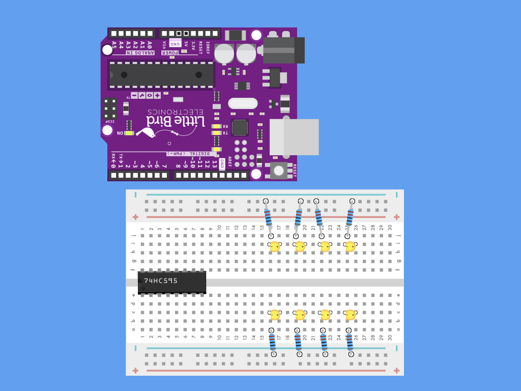
Next, connect resistors to the negative lead of the LEDs.
Connect the other side of the resistors to the negative power rail.
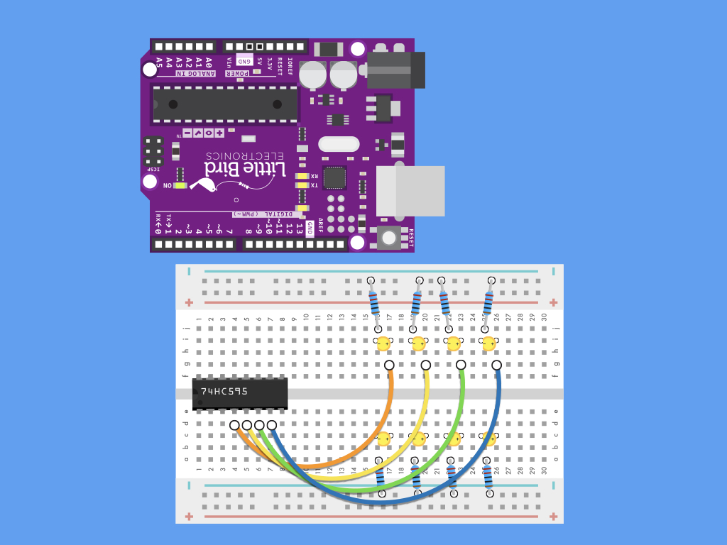
First, let's make connections to the LEDs on the upper row. Connect their positive lead to Pins 4,5,6 and 7 of shift register.

Next, make connections to the LEDs on the lower row. Connect their positive leads to Pins 15, 1,2 and 3 of the shift register.
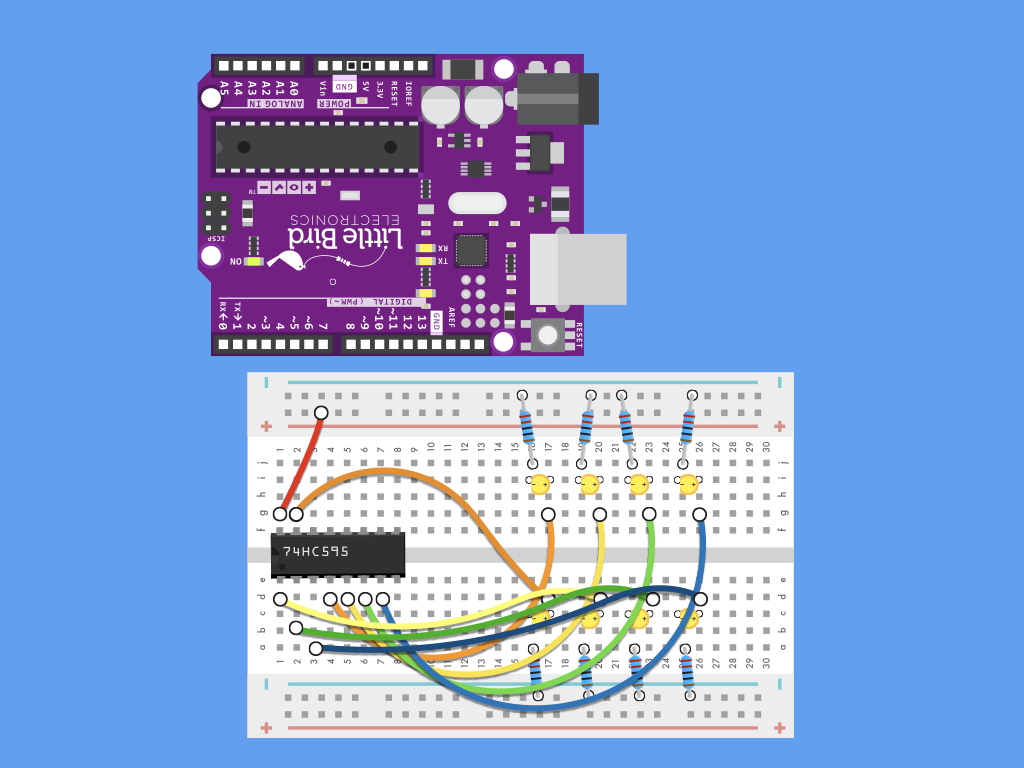
Connect Pin 16 (VCC) of the shift register to the breadboard's positive power rail.


Connect Pin 10 of the shift register to the positive power rail.
Finally, complete the circuit by first connecting the positive power rail on both ends of breadboard
Connect negative power rail on both ends of breadboard
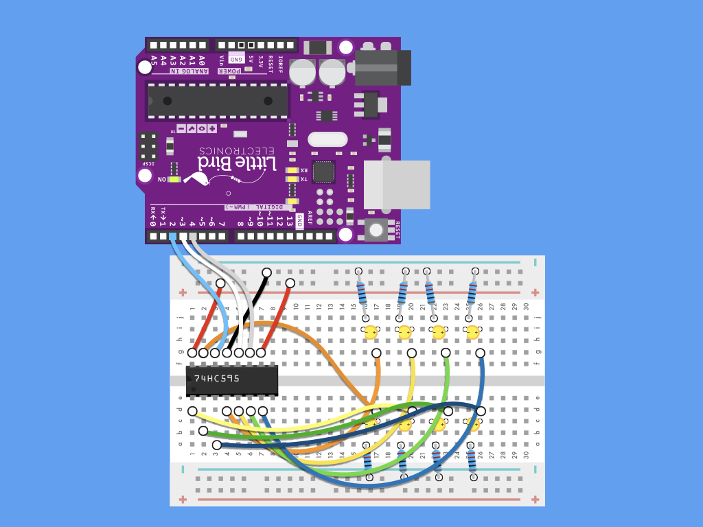
Connect positive power rail to 5V of Arduino
Connect negative power rail to GND of Arduino
Connect Pin 8 of shift register to negative power rail
int latchPin = 4;
int clockPin = 3;
int dataPin = 2;

byte leds = 0;

void setup()
{
  pinMode(latchPin, OUTPUT);
  pinMode(clockPin, OUTPUT);
  pinMode(dataPin, OUTPUT);
}

void loop()
{
  leds = 0;
  delay(500);
  for (int i = 0; i < 8; i++)
  {
    bitSet(leds, i);
    digitalWrite(latchPin, LOW);
    shiftOut(dataPin, clockPin, LSBFIRST, leds);
    digitalWrite(latchPin, HIGH);
    delay(500);
  }
}
Upload this code to the Arduino and watch the LEDs light up one after another.
How it works:
- First, we defined the following at the top of the Arduino sketch:
- The latch, clock and data pins.
- A byte called 'leds' that will store the bits, and will let the shift register know which outputs to use.
- Next, in void setup(), we initialised the pin modes to be OUTPUT for latchPin, clockPin, and dataPin.
- In void loop(), the leds variable is cleared at the start of each iteration.
- A for loop() is used.
- The bitSet() method is used, and the byte we are using to store the bits in, leds, is passed through.
- This method allows us to set individual bits of the byte to '1' by specifying its position.
- That is to say, with each increment, we are also setting the bit to the left of the previous one to 1 every time.
- After the bits have been set, we write to the latchPin to indicate that data is about to be sent.
- Once this is complete, the shiftOut() method is used.
- Its first two parameters are dataPin and clockPin,
- Its third parameter tells the method in which order to shift out the bits; it can be either LSBFIRST (least significant bit first) or MSBFIRST (most significant bit first). The least significant bit is the right-most bit, and the most significant bit is the left-most bit.
- Its fourth parameter is the byte which contains the bits that we actually want to shift to the shift register.
- Next, we write HIGH to the latch pin to indicate that all the data has been sent.
- Finally, we add a delay of half a second or 500 milliseconds.
int latchPin = 4;
int clockPin = 3;
int dataPin = 2;

byte leds = 0;

void setup()
{
  pinMode(latchPin, OUTPUT);
  pinMode(clockPin, OUTPUT);
  pinMode(dataPin, OUTPUT);
  Serial.begin(9600);
}

void loop()
{
  leds = 0;
  delay(500);
  for (int i = 0; i < 8; i++)
  {
    Serial.println(leds);
    bitSet(leds, i);
    digitalWrite(latchPin, LOW);
    shiftOut(dataPin, clockPin, LSBFIRST, leds);
    digitalWrite(latchPin, HIGH);
    delay(500);
  }
}
If you'd like to output the value of the variable, leds to the serial monitor, you can do so by adding:
Serial.begin(9600); to void setup()
Serial.println(leds); in void loop()
Open up the serial monitor in the Arduino IDE. You should see 0 followed by 1, then 3, and then 7, then 15, then 31, then 63, and finally 127.
Decimal to Binary:
0 = 0
1 = 1
3 = 11
7 = 111
15 = 1111
31 = 11111
63 = 111111
127 = 1111111
To see the output values in binary, modify the Serial.print(); statement to Serial.println(leds, BIN)
int latchPin = 4;
int clockPin = 3;
int dataPin = 2;

byte leds = 0;

void setup()
{
  pinMode(latchPin, OUTPUT);
  pinMode(clockPin, OUTPUT);
  pinMode(dataPin, OUTPUT);
  Serial.begin(9600);
}

void loop()
{
  Serial.println(leds, BIN);
  bitSet(leds, 1);
  bitSet(leds, 7);
  digitalWrite(latchPin, LOW);
  shiftOut(dataPin, clockPin, LSBFIRST, leds);
  digitalWrite(latchPin, HIGH);
  delay(500);
}
To light up particular LEDs or let's say you wanted to manually set the binary value to be '10000010' :
The bits we want to set to '1' are the second from the right, and the left-most bit.
To do that, simply use bitSet(leds, 1); and bitSet(leds, 7);
Remember, the first position is position 0, and Position 7 is the most significant bit (left-most bit)